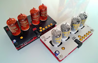
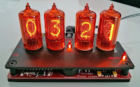
Ten years ago I built my first presentable Nixie tube digital clock. A 'what' tube clock? A Nixie tube is a vintage readout device used in digital displays, before 7-segment LED and LCD displays took over. All ten digits in a Nixie tube are perfectly formed and covered by orange neon glow when lit. All a 7-segment display is capable of is an unattractive bunch of horizontal and vertical lines. Anyway, here is a ten year old picture of my Nixie clock.
Some features of the clock:
- selectable 24-hour time format or 12-hour time format with AM/PM indicator,
- date can be displayed in DD-MM or MM-DD format, with leap year correction,
- the clock will run with no power supply connected (with display switched off),
- display brightness is adjustable (in 16 steps),
and some non-features:
- no alarm (In my opinion also unnecessary, no one should be hitting those fragile Nixie tubes at 5.30 in the morning.),
- limited timekeeping accuracy (Which is still very good, with the high precision 32.768kHz crystal used.),
- no automatic DST correction option (too many confusing policies in different countries),
- no case (just yet...).
Yep, it didn't have a case back then. And, if you like geeky gadgets (like me), you might say it doesn't need one. It is/was a slight hazard to handle though. Neon in a Nixie tube requires at least 170V to ignite, and for that reason there is 190V present on some parts of the board. Not lethal (due to limited current capabilities), but very unpleasant to touch!
This clock needs a case!
Today, 10 years later, I've decided to revive the project. I still have a limited stock of ZM1000 Nixie tubes (and their original sockets) available, plus I also have several bare PCBs left. Only this time I'll add a case. That's what I call slow progress!
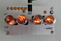
Well, kind of a case anyway; the clock has to maintain its geeky gadget status, but it also has to be 'safe' to handle, and, most importantly, the case is to be constructed by someone with very limited case design abilities (me). In the end, I've decided that two laser-cut aluminum or acrylic sheets to cover the top and bottom of the PCB will do the trick. Not very classy, but still an aesthetically pleasing and compact case substitute. Pictures below show the clock in a rough prototype case with two laser-cut acrylic sheets. The final version will feature precision laser-cut anodized aluminum sheets. Also, two small neon lamps will be added, one as the blinking seconds indicator, the other as an AM/PM indicator.
The variant below is the one SWMBO prefers - no blinking, neon lamps removed.
Some more views...
... and two newly built clocks with red solder mask PCBs, one with red coated ZM1000R tubes and one with clear ZM1000 tubes.
Those ZM1000Rs with red contrast filter look stunning!
Some technical stuff
I will only briefly describe the inner workings of this clock. I would be more that willing to share the schematic file, but I don't have it anymore. (In 2005 I wasn't paranoid enough to do backups. Today, I am a little more paranoid. Moreover, I know better.) The main feature of the clock is its display: four ZM1000 Nixie tubes seated on their original sockets. As the clock is powered by a standard wall-plug 9VDC adaptor, the 190V supply for Nixie tubes is generated on board with a boost converter built around the MAX1771 controller. The timekeeping is done with the DS1302 RTC IC and an 1F backup capacitor. (Therefore, the clock will keep the time even with no power connected.) Two vintage 7441/74141 TTL ICs are used to drive the Nixie tubes.
The heart of the clock is an ATtiny2313 AVR micro-controller; it reads from and writes to the RTC, reads the state of the three tactile switches, and drives the 2x2 multiplexed Nixie display. Programming the micro-controller was the biggest challenge. The features I wanted: an intuitive time-and-date setting procedure, cross fading digits (display gently changing from old to new value), and adjustable display brightness. (Plus, the non-negotiable requirements: switches debounce routine, multiplexed display refresh routine - 100x times per second, and routines to communicate with the RTC.) The ATtiny2313 micro only has 2k of flash memory (into which you can fit 1k RISC instructions) so it had to be programmed in bare AVR assembly. (... and I learned this the hard way!)
For those interested: this is the EAGLE PCB file. Note that some element values may be missing from the PCB. (And, as already mentioned, I do not have the EAGLE schematic file anymore.) I am unwilling to share the program for the AVR micro just yet...


